A "Current" Use For Old Insulators
by Mike Bowen
Reprinted from "Crown Jewels of the Wire", November 1993, page 20
The following is an article I wrote for the "Tesla Coil Builders
Association" newsletter that publishes unique information on Nikola Tesla
and his discoveries, high frequency-high voltage experimentation, and other
related topics.
VACUUM TUBE TESLA COIL
This project actually began when I was in the 6th grade in 1965. I saw my
first Tesla coil at our school's science fair, and the next day, I ran to the
library and got a copy of the science projects book that detailed the
construction of a vacuum tube Tesla coil. Eventually, the plans and the amassed
parts were lost in the black hole that existed in my closet.
Many years later,
while leading an archeological expedition into the boxes that my parents had so
thoughtfully packed with my accumulated debris, I found those plans.. After 25
years, I decided to finish my project.
The original schematic was from Science
Experimenter, titled "New and Improved Tesla Coil". It was designed to
be simple in construction, low cost, and of small size. Because I wanted the
device to be displayed at a science fair (here I must admit that I have a son
who wants to follow in my footsteps; he wants to enter it next year), it had to
be visually exciting in order to compete with the many contemporary projects to
be seen at any modem fair. We built it on a wooden top, and spread the circuits
out so they could be identified. Legs were added and casters, so it could be
moved around in our electronics laboratory.
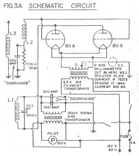
In the original schematics, a
standard, low cost plate transformer is called for. I obtained a 2000 volt transformer direct from the
engineering department at Thordarson. The familiar TV door-knob type capacitors
were very expensive, as well as the two 811-A triodes called for (I paid $72 for
just the tubes -- the three high voltage caps were $45).
I stuck with the design
in the prints for the construction of the coils. The primary is 18 turns of two
#14 wires wound in parallel. The grid coil is 18 turns of #20 wire, and both
coils are wound on a 4-1/2 inch PVC form. The secondary is about 1900 windings
of #32 magnet wire on a 2 inch O.D. form, 17-1/2 inches long.
We wanted to make
sure that the components were isolated from each other to prevent arcing and
feedback, but also give the board a kind of antique, sci-fi type of effect, to
help capture the attention of the folks that might like to ask questions and to
promote the experimentation that Tesla founded. This seemed to be a perfect time
for us to combine the two hobbies that we enjoy --- Tesla research and insulator
collecting.
Electrical insulator collecting has it's own following, and it is
really amazing how much effort goes into the hobby in the U.S., as well as
around the world. I have been collecting insulators for some years, and I own a
sizable number of them. They are proudly displayed for all to see and there are
also quite a few stories behind many of them. Insulators were (still are in some
places) used to separate the electrical wire carrying telephone, telegraph, or
line voltages and currents, from going to ground through the support poles or
suspension brackets. They come in many shapes and sizes, and almost as many different colors, with the variations in their manufacture due to end use. (For
further information, see the publication "Crown Jewels of the Wire",
P.O. Box 1003, St. Charles, IL 60174) [Editor: Thanks for the plug, Mike.]
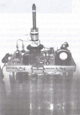
From
the photo on the previous page, notice the high potential terminal on the
secondary. It is a rubber insulator from a very old telegraph line. The two high
voltage capacitors in the power circuit are isolated on a porcelain insulator
that I picked up in Palma, Spain while I was in the Navy in 1985. Referring to
the schematic diagram, you see the grid circuit has a 2500 ohm 50 watt resistor
paralleled to a 500 picofarad cap. I have these suspended between two glass high
voltage mid-span transposition insulators for heat dissipation. There are also
two old telephone insulators that are holding the ground connection cable and
clamp, located on the project's left.
The antique appearance comes from the
addition of two old meters circa 1920, that I removed from an old power station
being tom down. The meter on the left is an AC voltmeter, and the right is an
ampmeter which incorrectly gives readings up to 180 amps when I engage the coil.
This was a real surprise to a few friends who didn't understand electronics but
who were impressed by the layout of the project. Mounted underneath is another
electrical display as an attention getter -- a 12,000 volt neon sign transformer
and a Jacob's ladder. It cranks up when the power transformer for the Tesla coil
is on. It's basically for the smaller kids to see.
Next to this is an antique
phase angle meter, and some day the meter will be hooked up to measure the phase
shift between the grid circuit, and the plate resonant circuit, when I can
figure out how to do it.
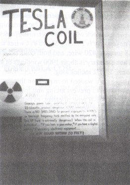
To complete the project for display at the science
fair, I constructed a large poster, and listed the dangers involved when the current is on and
the Tesla circuits are engaged. I purposely overstressed the high frequency
field generated, but the warnings I added about not bringing any electronic
equipment within 20 feet of the energized coils was a real danger. I burned up
my Timex digital watch and shorted out my father-in-Iaw's digital multimeter the
first few times I had the coil on. Also, a neighbor a few doors down is not real
happy with me. He claims he was operating his ham radio, talking to a friend in
Moscow, when the high frequency field effects shut him down. Do I believe him,
or not?
If my mathematics can be believed, the coil resonated at approximately
500 kHz, with a .0025 microfarad, 10,000 volt pulse industrial capacitor across
the primary. The high potential terminal can demonstrate a 10 to 12 inch
discharge, with the apparatus in a darkened room. Output is around 75,000 volts.
Nikola Tesla (1856-1943) was an American inventor, a prophet of science. He
is a forgotten genius, who revolutionized the science of electricity, and in a
burst of invention, he created the polyphase alternating current system of
motors and generators that power our world. He gave us every essential of radio,
and laid the foundation for much of today' s technology. The Tesla coil project
is but a shadow of Tesla' s giant Wardencliffe transmitting tower, still
partially standing in New Jersey. It would have provided free electrical power
around the planet had it been completed.
As an interesting footnote, when Tesla
died, the F.B.I. removed all of his diagrams and schematics from his office
safe. The United States government is even now using his original research in
the generation of high voltage plasma fields for nuclear fusion reactors. (If
you have further interest, read "Tesla, Man Out Of Time", by Margaret
Cheney)
| 
)
)
)